TEST KEEP CLOSED
MECHANICS
Mechanics
- The Monkey and The Hunter
- Simultaneously Shoot and Drop Pair of Spheres
- Projectile Launched Vertically from a Moving Cart
Newt's Laws of Motion
- Newton's First Law
- Newton's Second Law
- Newton's Third Law
- Blackboard Mechanics Kit
- Cork Bob Accelerometer
Work and Energy
- Bowling Ball Pendulum
- Blocked Pendulum
- Loop-The-Loop
- Coefficients of Friction
- Friction Cart
- Energy Stored in a Spring
Mechanical Equilibrium
Collisions and Conservation of Momentum
- Explosions
- Totally Inelastic Collisions
- Elastic Collisions
- Newton's Collision Apparatus
- Internal Degrees of Freedom
Circular Motion
- Balls in Rotating Cups
- Loop-the-Loop
- Elastic Collisions
- Swinging Water Bucket Overhead
- Conical Pendulum
Rigid Body Rotations
OSCILLATIONS AND WAVES
Periodic Motion
Driven Oscillations and Resonance Phenomena
- Driven, Damped Harmonic Oscillator
- Resonance with a Speaker and Adjustable Pipe
- Driven Pendulum
- Modes of Vibration
- Compound Pendulum
- Chaotic Oscillations
Propagation of Mechanical Waves
Superposition of Waves
Normal Modes of Vibration
Acoustic Phenomena
OPTICS
Geometrical Optics
- Blackboard Optics Kit
- Dispersion in a Prism
- Total Internal Reflection
- Fiber Optic Cables
- Speed of Light
Interference and Diffraction
- Single Slit
- Double Slit
- Multiple Slits and Gratings
- Thin Film Interference:
- Newton's Rings
- Poisson's Spot
- Michelson Interferometer
Polarization
THERMAL PROPERTIES OF MATTER
Thermal Expansion
Thermal Conductivity
THERMODYNAMICS
Pressure-Volume-Temperature Relationships
- Adiabatic Gas Law
- Pressure Differences
- Model Lung
- Boyle's Law
- V-T Relationship at Constant Pressure
- P-V-T Surface for Water
- Diffusion Through an Aperture
- P-T Relation at Constant Volume
Many Particle Systems
ELECTRICITY & MAGNETISM
Electric Charge and Field
- Positive and Negative Charge by Friction
- Induced Surface Charge on Conductors
- Coulomb's Law
- Distribution of Surface Charge on Conductors
- Capacitors and Energy Storage
- Capacitance vs. Plate Separation
- Van de Graaff
- Jacob's Ladder
- Electric Field Lines
- Force on a Moving Charge in an Electric Field
- Flux Surface and Volume
Current and Resistance
- Resistors in Series and Parallel
- Internal Resistance of a Battery
- Ohmic and Non-Ohmic Devices
- Drift Velocity Demonstrator
- Wire Fryer (DC version)
Magnetic Field and Forces on Currents
- Magnetic Domain Model
- Magnetic Field of Permanent Magnets
- Earth's Magnetic Field: Dip Needle
- Magnetic Field of Currents
- Magnetic Field of a Solenoid
- Magnetic Force on an Electron Beam:
- Magnetic Force on a Current-Carrying Wire
- Magnetic Torque on a Current Loop
- Force Between Current-Carrying Wires
Induced Currents and EMF
- Faraday's Law and Lenz's Law
- Enclosed Fields and Magnetic Induction
- Current Generators
- DC Motors
- Eddy Currents:
- Jumping Rings
- Wire Fryer AC
- Transformers and Flux Linkage
- Self-Inductance and Energy Storage
- Displacement Current
Time Dependent Currents
Superconductivity
Electromagnetic Waves
ATOMIC AND NUCLEAR PROCESSES
Quantum Physics
Nuclear and Particle Physics
VISUAL AIDS
Michelson Interferometer
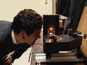
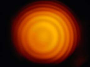
A color CCD camera and video monitor are used to display the interference pattern produced by a Michelson interferometer illuminated by a sodium vapor lamp. The concentric ring pattern, shown in the photo on the right, results when the mirrors in the two arms of the interferometer are carefully aligned such that their normals are parallel to their respective beam paths. Changing the length of one of the beam paths will then cause interference rings to appear from or disappear into the center of the pattern. If the mirrors are slightly misaligned, the image changes from concentric rings to more or less straight fringes, which move across the filed of view as the length of the beam path is changed. By counting the number of fringes which pass a given point in the field of view, and measuring the change in path length, the average wavelength of the sodium D-lines (589.3 nm) can be determined.

